When an O2 sensor fails or generates an erratic/out-of-range signal, the PCM will resort to using a predetermined, conservative estimate in place of the real time reading. This can yield lower performance, fuel economy, and throttle response. When a sensor failure is detected, a diagnostic trouble code (DTC) and check engine light are typically set identifying the faulty O2 sensor. While it's perfectly acceptable to only replace the sensor(s) that have triggered a DTC (DTCs will vary, but generally pinpoint the bank and upstream/downstream position), we've always replaced the O2 sensors in sets to ensure the range of readings is equal between sensors.
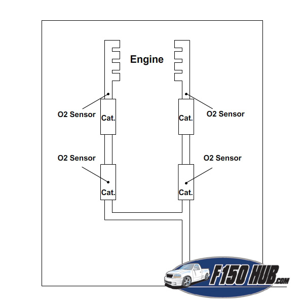
There are (4) O2 sensors on a 1997 - 2003 Ford F-150; two before the first catalytic converters on each bank of the engine and two inside each of the rear catalytic converters on each bank of the engine (see map below). The O2 sensors closest to the engine are referred to as "upstream" sensors, while the rearmost are referred to as "downstream" sensors. There is a difference between upstream and downstream sensors, so mind the correct part number(s) for your vehicle.
For each sensor, you'll need to 1) disconnect the electrical connector on the sensor pigtail, 2) remove the old sensor, 3) install the new connector using a liberal amount of anti-seize compound on the threads, and 4) reconnect the electrical connector. It is not uncommon for the threads in a sensor bung to strip - details on repairing the threads can be found below.
Click any thumbnail to view high resolution fullsize image w/ addition details (where applicable)
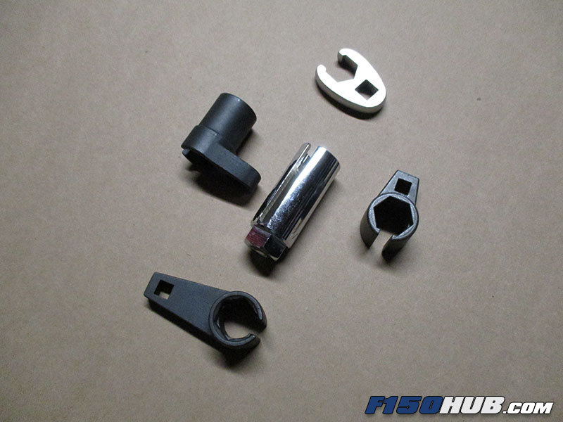
• The image at left gives you a general idea of the location of the O2 sensors. Each O2 sensor has a 22 mm nut at its base, but they will also accept a 7/8" tool. O2 sensor sockets are typically compatible with both 7/8" and 22 mm sizes. The hex head at the base of the sensor is extremely easy to round off with an open end wrench or crowfoot. It is highly advised that only O2 sensor sockets or a flare nut wrench/crowfoot is used to remove and install the sensors. To make matters worse, you can expect the sensors to be extremely tight in their bungs. You may need to access a range of tools in order to reach all the sensors - do not expect to reach them all with a simple wrench.
• Disconnect the negative battery cable.
• Referring to the image at left, there are a variety of 22 mm, 7/8" sockets and tools available to remove O2 sensors in confined spacers - a variety of these tools were required to remove and install the four sensors. Some sensor locations have greater spacial constraints than others.
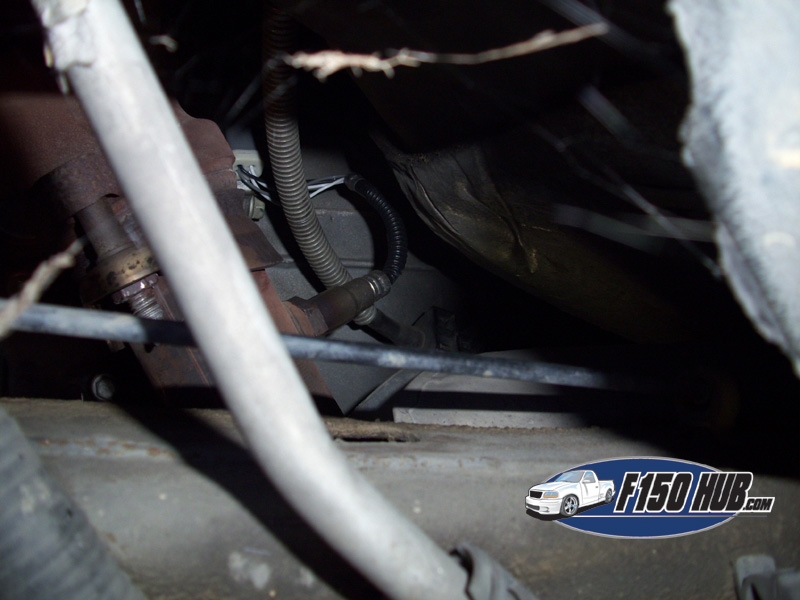
• Driver side front sensor - The front sensor on the driver side is fairly simple to remove with a 22 mm flare nut wrench. It is accessed from beneath the truck.
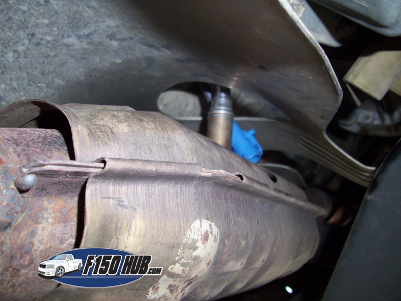
• Driver side rear sensor - Since this truck is 4 wheel drive, the transfer case limits access to the rear catalytic converter, which is where the O2 sensor is located. Loosening the exhaust clamp located behind the catalytic converter and unbolting the exhaust collector that connects the exhaust system to the exhaust manifold allowed us to lower a 2-3 foot section of the exhaust system that contains the two catalytic converters. This gave us just enough room to access the sensor, remove it with a 22 mm flare nut wrench, install the new sensor, and slide the exhaust back into place. This may not be required for all applications, but it made the task much easier in this case.
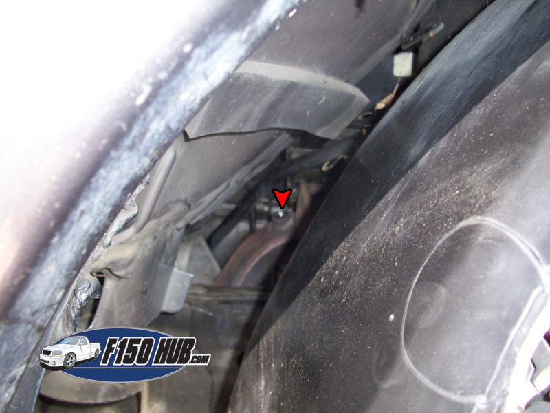
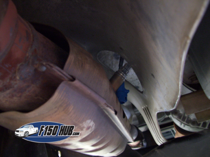
• Passenger side front sensor - The passenger side front O2 sensor is located directly behind the exhaust collector where the exhaust manifold connects to the exhaust system. This truck has the sensor pointing upwards, but some trucks will have the sensor pointing inward. Removal of the inner fender (plastic liner inside the front fender) as well as the transmission dipstick tube may be required. We were able to remove this sensor by unfastening half of the inner fender and pulling it out of the way. This is generally the most time consuming sensor to remove due to its location, so be prepared to use all the tools in your arsenal.
• Passenger side rear sensor - Accessing this sensor is similar to accessing the driver side rear, but without having to disconnect the exhaust system. You may choose to remove the catalytic converter heat shield, but we did not have to.
O2 Sensor Bung Thread Repair
If the threads of the O2 sensor bung become damaged and the new sensor will not thread into place, you'll need to chase the threads with a tap. It is relatively common for the threads to become damaged after removing a stubborn sensor - these are subjected to thousands of heating and cooling cycles over the course of their life and tend to become stuck.
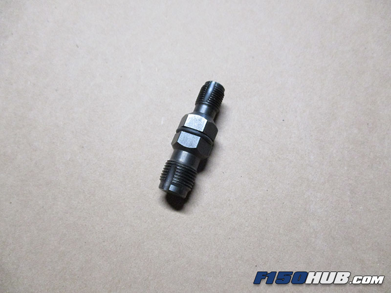
The threads are M18 x 1.5 and a special tap is available that is designed to fit into tight locations. One example is Lisle 12230 (see link for details). A normal tap is difficult to use as it will not fit in most cases due to spacial limitations. The dedicated tool is much shorter and works with a socket/wrench instead of a standard tap handle.
Chase the threads using a liberal amount of cutting fluid (or even motor oil) on the cutting teeth of the tap. Be sure to clean the threads by frequently backing the tap out a full turn for every 1 to 2 cutting rotations. Once the threads have been repaired, clean the area thoroughly and wipe any oil from the exhaust tubing with a rag and a solvent (brake cleaner, carb cleaner, etc).